How Are Vias Incorporated Into the Rigid-Flex PCB Fabrication Process?
Rigid-Flex PCB Fabrication Process
Rigid-flex circuit boards are typically used in industrial and medical devices, such as hearing aids, pacemakers, and diagnostic tools. They are also utilized in military/aerospace and automotive applications. They have unique mechanical properties that allow them to withstand vibration and shock. However, this uniqueness also carries with it a number of different potential failure modes. These include thermal cycling, vibration, and stress. To ensure a high level of reliability, proper design is key. Careful consideration must be given to materials, assembly processes, and test points to reduce the risk of unique failure modes.
A rigid flex pcb fabrication begins with a conductive layer. Usually, this is copper foil. This layer is bonded to the base material with an adhesive, most commonly epoxy resin or polyimide film. A dielectric is then applied, which typically is a layer of FR-4. Finally, a layer of copper is applied to the entire surface. This copper is then plated with nickel and etched to create the conductor pattern.

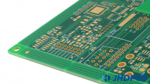
Once the copper patterns are etched, holes to vias and pads are mechanically drilled. This process is known as routing. There are a few different ways to perform this step, but hydraulic punching is generally preferred due to its precision and ability to cut multiple pieces at one time. This is particularly important in cases where the flex board is being made with small-production runs.
How Are Vias Incorporated Into the Rigid-Flex PCB Fabrication Process?
Afterward, the flex boards are assembled to their rigid counterparts in a process called lamination. This is a critical step in the process, since the bond between the two can be compromised by poor handling or by the use of improperly calibrated equipment. In order to prevent the flex board from becoming unattached during this process, it is critical that all holes are aligned properly and all layers are bonded together with the proper amount of pressure.
To further enhance the reliability of a rigid-flex circuit, it can be finished with solder mask and a coverlay. Solder mask is a photo-imaged liquid epoxy that protects the copper from contamination and exposure. Similarly, the coverlay is a polyimide film with adhesive and protects the flex circuit from harsh environmental conditions.
Once these layers have been bonded and laminated, the final outer layers of copper foil are plated and etched, which completes the circuit. It is then ready to be tested for functionality and durability.
During testing, it is important to ensure that the flex and rigid sections are not repeatedly bent past their specified bend radius, which can lead to conductor cracking or insulation failure. Careful mechanical modeling can help prevent this from occurring, as can adding tabs to the flex structures to stop them from peeling. Additionally, using a metallurgical coating that can resist harsh environments can also help prevent this from occurring. Lastly, avoiding the use of any adhesives can reduce the chances of cracking during reflow soldering.